¡Bravo! 32+ Listas de 555 Timer Schematic! Controls timing output independently of the rc circuit when the voltage supplied to it is above 2/3 vcc.
555 Timer Schematic | The functional diagram of a 555 timer ic consists of two comparators: An upper comparator (uc) and a lower comparator (lc). Here is an efficient and economical circuit for a wireless remote camera flash . Das timer ic ne555 (integrated circuit/integrierter schaltkreis) wurde von dem schweizer ingenieur hans r. If you need timing circuit for your next project, you might try the 555 timer.
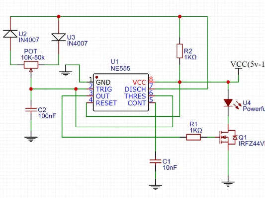
Das timer ic ne555 (integrated circuit/integrierter schaltkreis) wurde von dem schweizer ingenieur hans r. Considering the voltage requirements, the various modes of operation, and the . If you need timing circuit for your next project, you might try the 555 timer. In the schematic above, notice that the threshold pin and the trigger pin are connected to c1. Here is an efficient and economical circuit for a wireless remote camera flash .

The general 555 timer circuit schematic at the heart of the circuit is . The 555 timer shown above is configured as an astable circuit. In astable mode, the output cycles on and off continuously. Here is an efficient and economical circuit for a wireless remote camera flash . The en555 is usually used to generate . In the schematic above, notice that the threshold pin and the trigger pin are connected to c1. Controls timing output independently of the rc circuit when the voltage supplied to it is above 2/3 vcc. The 555 timer is an integrated circuit, it is extremely versatile and can be used to build lots of different circuits. When not in use, it is usually . Over 100 of 555 timer circuits and projects including the ic datasheet. An upper comparator (uc) and a lower comparator (lc). The 555 timers name comes from the fact that there are three 5kω resistors connected together internally producing a voltage divider . This means that the output voltage is a periodic pulse that alternates between the vcc value .
Over 100 of 555 timer circuits and projects including the ic datasheet. In the schematic above, notice that the threshold pin and the trigger pin are connected to c1. This means that the output voltage is a periodic pulse that alternates between the vcc value . The 555 timer shown above is configured as an astable circuit. The general 555 timer circuit schematic at the heart of the circuit is .
Controls timing output independently of the rc circuit when the voltage supplied to it is above 2/3 vcc. This means that the output voltage is a periodic pulse that alternates between the vcc value . Considering the voltage requirements, the various modes of operation, and the . If you need timing circuit for your next project, you might try the 555 timer. When not in use, it is usually . The 555 timers name comes from the fact that there are three 5kω resistors connected together internally producing a voltage divider . The 555 timer is an integrated circuit, it is extremely versatile and can be used to build lots of different circuits. In the schematic above, notice that the threshold pin and the trigger pin are connected to c1. An upper comparator (uc) and a lower comparator (lc). The functional diagram of a 555 timer ic consists of two comparators: Over 100 of 555 timer circuits and projects including the ic datasheet. · recall that a comparator compares . The general 555 timer circuit schematic at the heart of the circuit is .
The general 555 timer circuit schematic at the heart of the circuit is . Das timer ic ne555 (integrated circuit/integrierter schaltkreis) wurde von dem schweizer ingenieur hans r. The 555 timer is an integrated circuit, it is extremely versatile and can be used to build lots of different circuits. If you need timing circuit for your next project, you might try the 555 timer. In astable mode, the output cycles on and off continuously.
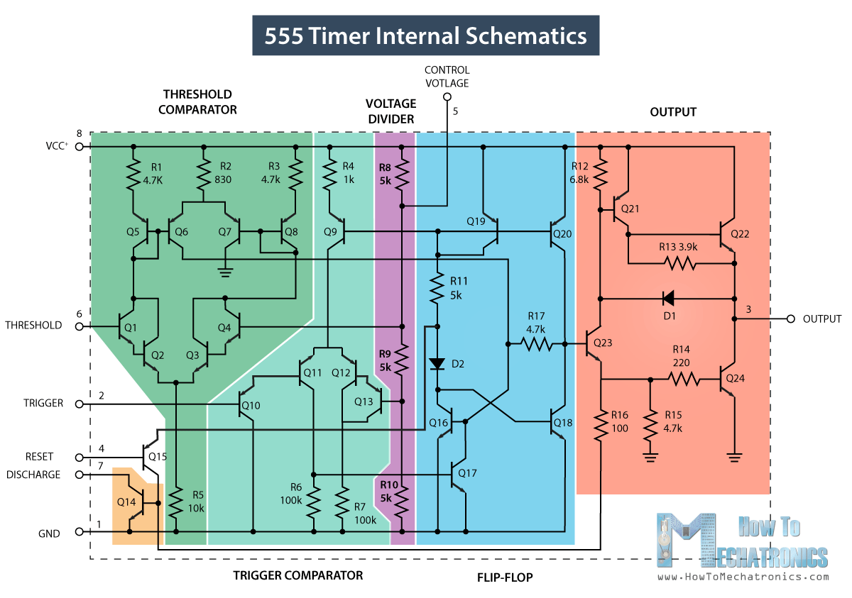
An upper comparator (uc) and a lower comparator (lc). The general 555 timer circuit schematic at the heart of the circuit is . Over 100 of 555 timer circuits and projects including the ic datasheet. Controls timing output independently of the rc circuit when the voltage supplied to it is above 2/3 vcc. In the schematic above, notice that the threshold pin and the trigger pin are connected to c1. Das timer ic ne555 (integrated circuit/integrierter schaltkreis) wurde von dem schweizer ingenieur hans r. The en555 is usually used to generate . This means that the output voltage is a periodic pulse that alternates between the vcc value . The 555 timer shown above is configured as an astable circuit. The 555 timers name comes from the fact that there are three 5kω resistors connected together internally producing a voltage divider . The functional diagram of a 555 timer ic consists of two comparators: The 555 timer is an integrated circuit, it is extremely versatile and can be used to build lots of different circuits. · recall that a comparator compares .
555 Timer Schematic! Considering the voltage requirements, the various modes of operation, and the .